DOING Holdings
DOING Holdings
A properly built and properly run pyrolysis machine is safe to operate. The process itself — heating shredded tires or plastics without oxygen until they release oil, gas and carbon black — contains no explosion risk as long as the three sides of the fire triangle never share the same space: fuel is locked inside the reactor, oxygen is locked outside it, and heat exists only in the furnace wall between them.
Problems begin when one of those separations fails. In practice that happens in only four ways: air sneaks in at an opening, pressure builds behind a blockage, gas flows backwards along a pipe, or combustible dust escapes at discharge. Every serious incident in this industry traces back to one of these four, which is why safety is less about adding gadgets to a quotation and more about cutting off four paths at the source.
Below, each path is matched to the design features, devices and operating routines that close it — the same checks our engineers at DOING ECO (Henan DOING Environmental Protection Technology Co., Ltd) apply when configuring a pyrolysis machine for a customer's site.
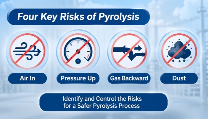
Four key risks of pyrolysis
Oxygen is the one ingredient the reactor must never receive. Once fuel and heat are already present, air is the only missing side of the triangle, and a pyrolysis machine has only a handful of places where it can enter. Each one needs its own closing method, and each method depends on an operating habit to stay effective.
The feed door. On a batch pyrolysis machine this is the biggest hole in the system — typically 1.4 m across. A flange ring with 32 bolts clamps it shut, and the sealing agent is a graphite packing rope seated in a machined groove. Graphite suits this job because of one property: it expands as temperature rises, so the hotter the reactor runs, the harder the joint clamps itself — the opposite of an ordinary gasket, which relaxes and weeps as it heats. What graphite cannot do is compensate for a skipped procedure. As the shell warms toward operating temperature the bolts relax slightly with the expanding steel, so the crew re-tightens them by hand at around 100 °C, a five-minute pass that belongs at the top of every heat-up checklist.
The feed screw. Semi-continuous and fully continuous configurations remove the door altogether. Material travels in through an enclosed screw feeder and a ball valve arranged in series, so the reactor is never opened to the atmosphere while it is hot. The benefit is not only a cleaner floor — it is that the oxygen barrier never has to be re-established, because it is never broken.
The feed itself. This is the detail most buyers miss: on a continuous pyrolysis machine, the screw and valve only form a seal when the material packs tightly as it passes. Rubber powder at 16–18 mesh, or plastic pieces smaller than about 30 mm, consolidates as it moves and holds the line. Chunky feed — un-shredded blocks, whole tires fed where they were never meant to go — rides through loose and drags air in behind every turn. Moisture causes a different failure: the instant water meets the hot wall it flashes to steam, and inside a sealed reactor that steam has only one exit, appearing as pressure at the outlet. Oil sludge is dewatered to below roughly 30% moisture before feeding for the same reason. Feed preparation is a safety procedure, whatever the quotation calls it.
Every small port. Discharge ports, sight glasses, thermowell fittings — each closes with packing or gaskets that age under daily heat cycles. A weekly walk-round that looks and feels for weeping seals, and re-packs them on the spot, keeps these minor openings minor. A seal that passes gas is invisible and continuous; the weekly habit is what makes it visible.
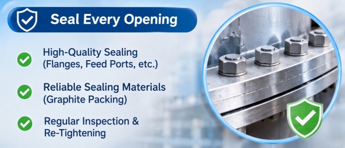
Pyrolysis machine high-quality sealing
The reactor operates at atmospheric pressure — in normal running, slightly below it, held by a negative-pressure system — so overpressure is not a design condition but an accident condition. It develops in exactly one scenario: gas continues to be produced upstream while the path downstream narrows. Two narrows account for nearly every case.
| Blockage | Why it forms | Engineered answer |
|---|---|---|
| Carbon black in condenser tubes | Fine black powder travels with the vapour and settles in the coldest, narrowest passages | Generously staged condensers, plus a cleaning interval written into the maintenance plan |
| Wax on pipe walls | Oil derived from plastics begins to solidify near 20 °C; long or cool pipe runs coat themselves from the inside until the passage closes | A dewaxing tank or secondary damping tank ahead of the condensers, larger pipe diameter, and short, hot pipe runs |
The device that stands in front of both is the buffer tank at the reactor outlet. It is an expansion volume with three duties: slow the gas, absorb surges, and carry the protection hardware on its crown — an automatic relief valve and a pressure gauge. When flow spikes, the tank swallows it; when pressure crosses a set point, the valve opens before any weld or gasket is asked to hold it. An electric-contact pressure gauge mirrors the reading to the control cabinet and raises an alarm, so the crew hears about a rising trend minutes before it becomes an emergency. Ask to see the panel, not the brochure — a gauge the operator cannot see from the operating position protects nobody.
The structural half of pressure safety lies in the shell itself, and it is where two manufacturers' machines diverge most.
The head. DOING ECO forms each reactor head as a single ellipsoidal piece, hot-spun to the GB150 pressure-vessel standard. Compared with a head assembled from several plates and welded onto the shell by hand — the joint lands out of plane, in the most stressed position on the machine, and cannot be machine-welded — the one-piece formed head carries roughly double the safety margin.
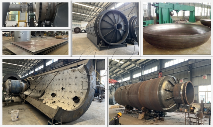
DOING ECO pyrolysis machine reactor head design
The weld. The head joins the shell through a specific angle groove with full penetration, laid down by automatic submerged arc welding. The groove runs at least 10 mm deep, and the finished weld measures about one and a half times the plate thickness. The plate is Q245R boiler steel, around 16 mm on a 15-tonne-per-day reactor; its lower carbon equivalent holds up better against the wet hydrogen sulphide corrosion that tire pyrolysis produces than the higher-strength Q345R would. Steel plates made of 306/316 stainless steel are also available upon request.
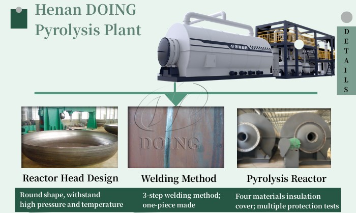
DOING ECO pyrolysis reactor design details
The supports. At the front, the shell rides on cast-steel rails with an air gap that keeps the trunnions cool and leaves room for thermal expansion. At the rear, a carriage with a locking groove holds the shell axially. That groove answers a slow-motion problem: over a year of heating and cooling the shell tries to creep backwards, and if nothing stops it, it pulls on the gas outlet — the hottest, most loaded joint on the machine. The groove takes that load instead.
The skin. Behind a refractory lining rated above 1,580 °C sits a layer of non-combustible rock wool, which holds the outer surface near 50 °C: warm against a palm, harmless to a worker, and far enough from ignition temperature that a stray contact is a first-aid matter rather than an incident report.
The negative-pressure device completes the set. By holding the shell slightly below atmospheric, it biases every small leak inward — air pulled toward the vacuum rather than gas pushed into the workshop. It is a layer that works with the water seals and relief valves, not instead of them.
The non-condensable gas is the quiet earner of the process — on a continuous pyrolysis machine it amounts to roughly 12% of output, and piped straight back to the furnace it displaces a large share of the fuel bill. It is also the most hazardous stream on the plant, for a simple geometric reason: a pipe that carries gas toward the burner can carry it back toward the reactor along the same wall. Three barriers make the reverse journey impossible in practice.
A water seal on the gas line. Reverse pressure simply bubbles through the water leg and vents; the water level is checked as part of the shift routine, because a seal is only a seal while it holds water.
A dedicated anti-backflow device. On DOING ECO machines this is a patented gas backflow safety device (patent no. ZL 2019 2 0093901.8) — a mechanical check that does not depend on anyone topping up a water level.
An oil seal at the feed inlet, which closes the last path of all: back through the very point where material enters.
Ignition order matters as much as flow direction. Burners fed by pyrolysis gas light electrically — at least two lances carry automatic ignition — so a flame always exists before fuel arrives at it. Manual lighting in the reverse sequence leaves a pocket of gas hunting for a spark, and on hot plant the spark is never far away.
One design rule removes half of these risks at a stroke: the gas is consumed, never stored. Gas bags and holders look convenient and fail twice — the gas composition drifts with every change of feedstock, and a stored volume of flammable gas is exactly what fire authorities assess hardest; many plants simply cannot pass the review. Burning the gas the moment it is produced, inside the furnace that generated it, means nothing on site can accumulate. Fleets put the surplus to work instead: the excess from one machine feeds the furnace of the next, which beats flaring on cost and storage on safety.
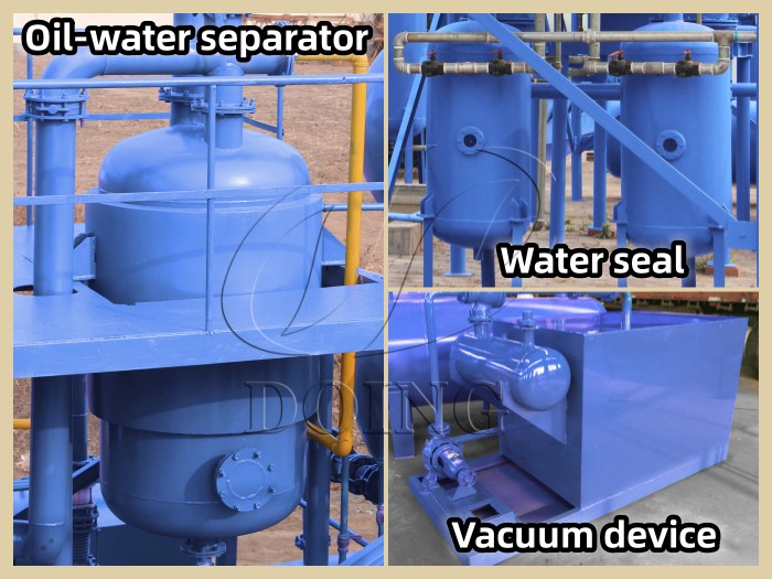
DOING ECO pyrolysis machine safety devices
The remaining two paths do their damage slowly, which is precisely why they get skipped.
Carbon black leaves sealed, or it doesn't leave. Discharge goes through a water-jacketed screw or directly into closed ton bags, so the powder never crosses the workshop air. Dust is a health hazard first — respirable, persistent — and a combustible-dust hazard second; both are answered by the same sealed path.
The flue chain is sized to the real gas volume. From the furnace outwards the sequence is fixed: coarse dust drops out first in a cyclone or air-cooled box, a pulse-jet bag filter catches the fines, a caustic spray scrubber strips sulphur, selective catalytic reduction at 280–360 °C handles nitrogen oxides, and activated carbon polishes the stream before the stack. Run inside that window, the catalyst clears over 90% of the nitrogen oxides — down past 50 mg/m³, with ammonia slip held under 3 ppm. The safety relevance is easy to miss: if this chain fouls or was undersized, pressure has nowhere to go but back into the vapour line, and section 2 happens all over again at the worst possible place. Two water rules protect it. Wash water never enters the furnace: oil-bearing water fed into the combustion chamber loads up the entire flue path, and once sulphur meets water the acid that forms eats the stack, the fan and the duct from the inside out. Scrubber water, meanwhile, is recirculated or sent through treatment — never dumped.
The panel and the kit. Between the extremes, instrumentation keeps the machine honest hour by hour.
| Device | What it reacts to | Where it sits |
|---|---|---|
| Pressure gauge and electric-contact gauge | Outlet pressure, with an alarm contact | Top of the buffer tank, repeated on the control cabinet |
| Temperature gauges | Vapour outlet, furnace, reactor door | Control cabinet, plus a door thermometer for discharge decisions |
| Automatic relief valve | Overpressure in the vapour or gas line | Buffer tank crown and the rear of the gas line |
| Double water seal | Reverse flow of gas | Gas line between the system and the furnace |
| Anti-backflow device and oil seal | Reverse flow at the gas line and the feed inlet | Gas line, feed inlet |
| Alarm bell | Any reading past its set point | Operator station |
| Forced-air cooling with vacuum | A reactor that must be opened before a full natural cooldown | Reactor shell |
| Emergency sand box | A small fire at a door or discharge port | Beside the reactor, within arm's reach |
Two of these earn a second look. Forced-air cooling brings a batch reactor down in 4–5 hours where natural cooling takes 10–12, and every hour cut from cooldown is an hour the crew is not tempted to crack a hot door. The sand box is deliberately primitive: a fire at an opening is smothered, not sprayed, because a water jet into a hot gas flow is how a local flame becomes a general one.
People close the last gap. None of the devices above runs itself, so before first start-up the crew that will actually operate the pyrolysis machine — not only the site manager — needs four things: what the normal panel picture looks like (outlet temperature and pressure, furnace temperature, cooling water flow), the burner lighting sequence, the response to a rising pressure trend, and the rules for opening the machine, which are about temperature and residual gas rather than the shift clock. On a batch machine that means opening once per cycle, below about 70 °C, with residual gas vented; on a continuous one it means never, because sealed feeding and water-cooled discharge keep the shell closed for its whole service life. DOING ECO delivers this training in person — commissioning is carried out by the factory's own engineers, who walk the actual crew through the actual valves and panels they will live with, not through a translated manual.
| Path | Closes it |
|---|---|
| Air in | Bolted door with heat-expanding graphite packing, or sealed screw and ball valve; feed kept to size and moisture specification; weekly seal walk-round |
| Pressure up | Buffer tank with relief valve and gauges; dewaxing tank and generous pipe sizing; GB150 one-piece head on full-penetration submerged-arc welds; grooved rear carriage; slight negative pressure |
| Gas backward | Water seal, patented anti-backflow device, feed-point oil seal; electric ignition with flame before gas; zero gas storage on site |
| Dust and heat | Sealed carbon black discharge; flue chain sized to real gas volume with SCR; wash water kept out of the furnace; full instrumentation; trained crew with reheated emergency drill |
Ask any pyrolysis machine manufacturer these four questions and the answers will separate serious builders from assemblers quickly: How is the door sealed while the reactor is hot? What opens first when pressure rises — the relief valve or the shell? What stops gas from running backwards? Where does the dust go? Vague answers to any of them are the cheapest inspection you will ever run.
If you would like the four paths mapped to a specific feedstock and tonnage, send the material, the form it arrives in, your daily capacity and your site conditions to DOING ECO. Our engineers will return a configuration with the safety chain itemized line by line, and the same engineers who designed it will install it and train your crew.
Below about 70 °C, after forced cooling and with residual gas vented. The forced-air system matters here: cutting cooldown from 10–12 hours to 4–5 removes most of the temptation to crack the door early — the most common cause of flash incidents at the feed opening.
Composition shifts with every batch of feedstock, which makes combustion control unreliable, and a stored volume of flammable gas is exactly what fire authorities assess hardest — many plants fail that review outright. Burning the gas as it is produced inside the furnace solves both problems and still displaces most of the fuel cost.
They make it unsuitable as designed feedstock. PVC and PET yield little oil and release corrosive compounds that attack seals, condensers and the scrubber chain, while their presence in a continuous feed stream undermines the screw seal that keeps oxygen out. Sorting them out at the source is a safety measure as much as a quality one.
Often enough that carbon black never narrows a passage to the point where outlet pressure trends upward — the pressure gauge is the indicator, not the calendar. Plants running clean, correctly sized feed typically clean between campaigns; plants running dusty or waxy feed tighten the interval and add a dewaxing tank rather than a warning sign.
A mild negative pressure is a useful extra layer, not a substitute for the rest. Holding the shell slightly below atmospheric means any small leak pulls inward rather than pushing gas outward. It works alongside the water seals and relief devices, and it should come from an engineered system designed for the reactor — not from improvised ducting added after delivery.